PKE Meter LED Pattern PCB
The PKE Meter LED Pattern PCB is very straightforward and can be done quickly depending on your soldering skills.
Here are your tools and supplies:
- Soldering Iron
- Soldering helping hands
- 0.3mm solder
- Tip tinner
- 1 Main Screen PCB
- 14 3mm green LEDs
- Wire cutters
- 1 3d printed screen insert
- 7 multi-colored wires – 30 AWG (silicone)
- 2 black wires – 30 AWG (silicone)
Step 1 – Wires
- Start by soldering wires through the holes marked 1 through 7 at the base of the PCB.


- Use a different colored wire for each hole so that you can clearly connect them to the corresponding hole when you get ready to connect it to the mainboard.
- Clean up all of the solder points and pads. Assure there are no hanging wires or threads that could create shorts.
- Get the 2 black wires and connect them to the GNDA and GNDB on the side of the PCB:
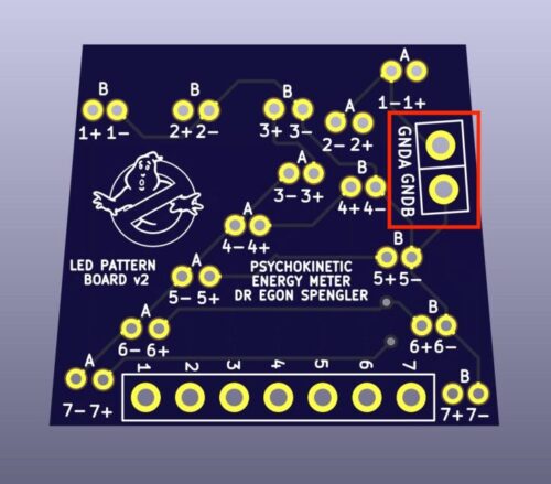
- Clean up the solder points on both of these black wires and pads. Assure there are no hanging wires or threads that could create shorts.
Step 2 – LEDs
- You can do this part two ways: Install the LEDs into the 3d printed holder, or Run the LED leads through the 3d printed holder and then through the PCB. I do it like this just to support the LEDs more. You can put the LEDs in the holder if you like, but the pattern is kept pretty tight with the PCB so it’s really not needed other than to install into the top PKE shell. The 3d printed screen insert will sit just a little more recessed down into the shell as a result. You’ll wan to make sure the green acrylic screen cover won’t bump into the LEDs.

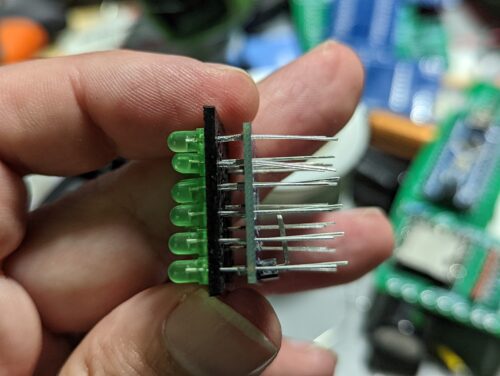
Make sure that the long wire goes through the hole that is marked with the + symbol. The shorter wire goes through the hole marked with the – symbol. - Each LED has a place on the wires that is indented or flattened towards the base of the LED. Try to fit the LEDs wires through to the PCB to this point or a little further if you can.

- Check that all of the leads are correct and in their correct holes. You should end up with something that looks like this:
- If you’d like, you can test the LEDs at this point to make sure they all light. To do this connect a battery to the PCB, the negative will connect to one of the black negative pattern wires. One by one, you can touch one of the colored wires to the positive on the battery. You should see an LED light up. Continue through all LEDs and then change to the other black negative wire. Go through the wires one more time, touching each one to the positive on the battery. You should see all lights turn on through both patterns.
- That’s it! The next step would be to connect this to the main board PCB.