PKE Meter Top Board
The PKE Meter top board might be the easier one of the PCB boards to assemble, but one of the more tricky ones to fit into place. You must be gentle when placing it in the PKE so none of the LEDs get bent.
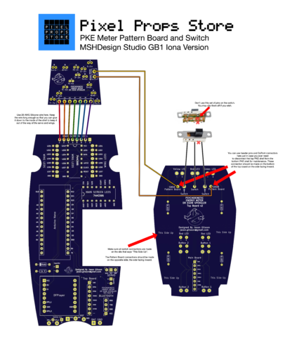
This is a diagram of top board and the placement of the components (except for the three way switch). Please read all of the directions before you assemble just to make sure you understand them. Always feel free to send a message on Facebook if you need guidance or have any questions at all.

LEDs
Next, thread the LED leads into the correct places on the PCB board on the side that says “This side up”. Do not solder them into place yet. Make sure the longer LED lead is in the hole marked with the + sign and the shorter lead is in the hold marked –.
Thread the stripped wires attached to the three way switch through the board paying close attention to the correct holes on the board. The grounding wire goes in the center.
Flip the board over and gently place the top edge with the three LEDs in the PKE Meter shell. Let the LEDs fit into the holes where they belong taking care to not force the board in. Once those LEDs are seated in place, drop the board into the PKE and use the LED leads on the two red LEDs to get them into place on the PKE shell. Once they are in place, drop the board all the way down into the PKE and push it flush with the inside of the shell. Solder all LEDs in place and clip the remaining lead wires off.
Three Way Switch
Strip both ends of the wire for the Three Way Switch. Solder the three pieces of wire into place on the switch. The main grounding wire is in the center.
Feed the wires into the top board PCB and dry fit the three way switch and board into the PKE meter to see how much wire is needed. Leave about 1/4 inch (6.35mm) and cut off the extra. Remove the board and and glue the switch into place. Once the glue is dry, feed the wires into the board and solder them into place.